- Sep 16, 2016
- 2
- 0
- 1
- 30

Current sensors are used when there is a need to measure the amount of current consumed by a certain appliance or device. There are several methods to measure the current flow and we are about to use Hall effect in our Current sensor switch circuit.
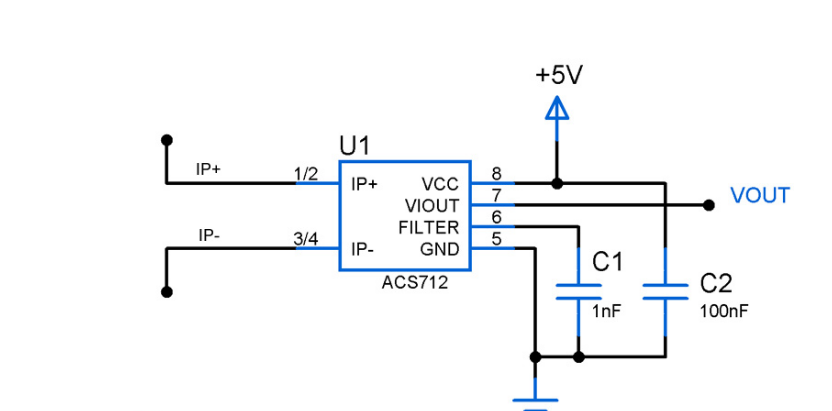
I use this IC ACS712 bought from http://www.kynix.com/Detail/743242/ACS712ELCTR-30A-T.html. It's a simple linear current sensor form the most significant part of this circuit.

WORKING OF CURRENT SENSOR CIRCUIT:
The Working is pretty straight forward, when current flows from the Pins 1,2 & 3,4 through the conduction path, it generates a magnetic field which is sensed by the hall effect sensor. This in turn converted into proportional output voltage. This equivalent output voltage will be obtained in the Pin 7 of the IC ACS712.
This type of Current sensor module will be useful for Microcontroller applications. The output from this circuit can be used with Analog pins of the Microcontroller and therefore precise value of current flow can be determined.

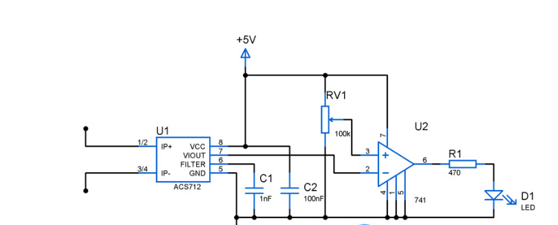
We can convert the current sensor circuit to a switch circuit by adding a simple stage of Op Amp along with it. The above circuit is a current switch toggles the output state whenever current exceeds a certain limit in their flow.
The reference value was set using variable resistor RV1 which feeds the non inverting input by preset level, whereas the output from the sensor IC was fed to inverting pin of the Op Amp. When the output voltage of IC is less than the preset value the output of Op amp remains high. The moment VIOUT exceeds the preset voltage Op amp toggles the output to low state. A LED was added as an indicator in the above circuit diagram you might also use relay provided sufficient power to drive it.
We can make it work the other way around that is make Op Amp gives logic 1 when current reaches preset value or logic 0 when it is below preset value. This can be done by simply swapping the inverting and non inverting pins of the Op Amp.

